Eventuri BMW Carbon Performance Intake F06 F12 F13 M6 – EVE-F1XM6-INT
BMW F13 M6
The F12/F13/F06 M6 intake system was developed through extensive dyno testing, maximum velocity tests and flow optimisation. We have developed a complete system from front air scoops to filter housings and even inlet tubes to the turbos. The resulting system is very efficient and reduces the resistance to the turbos by giving a smooth path for the airflow to travel through.
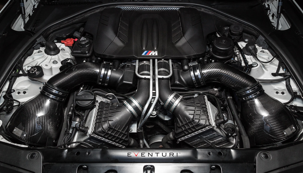
The Eventuri F10 M5 intake system consists of a number of components engineered to perform a specific purpose and fabricated to the highest of standards. Here are the details for each component and the design ethos behind them:
Each intake system consists of:
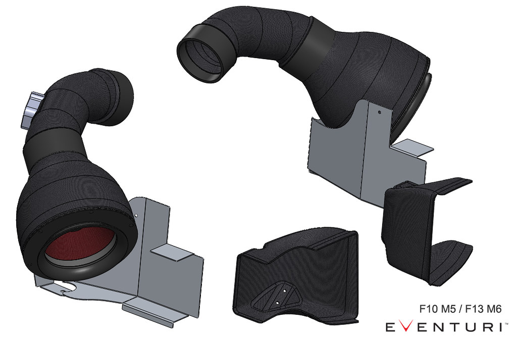
- 2 Carbon Fibre Venturi housings
- 2 High Flow Double Cone Air Filters
- 2 Aluminium Cowls for smooth airflow entry
- Left Side Carbon Tube with integrated MAF sensor mount
- Right Side Carbon Tube with integrated MAF sensor mount
- 2 Carbon Fibre Front Scoops
- 2 Laser Cut Aluminium Shields with integrated flow deflectors
- High quality Silicon couplers with BMW specification hose clamps
Carbon Intake Housing Assemblies
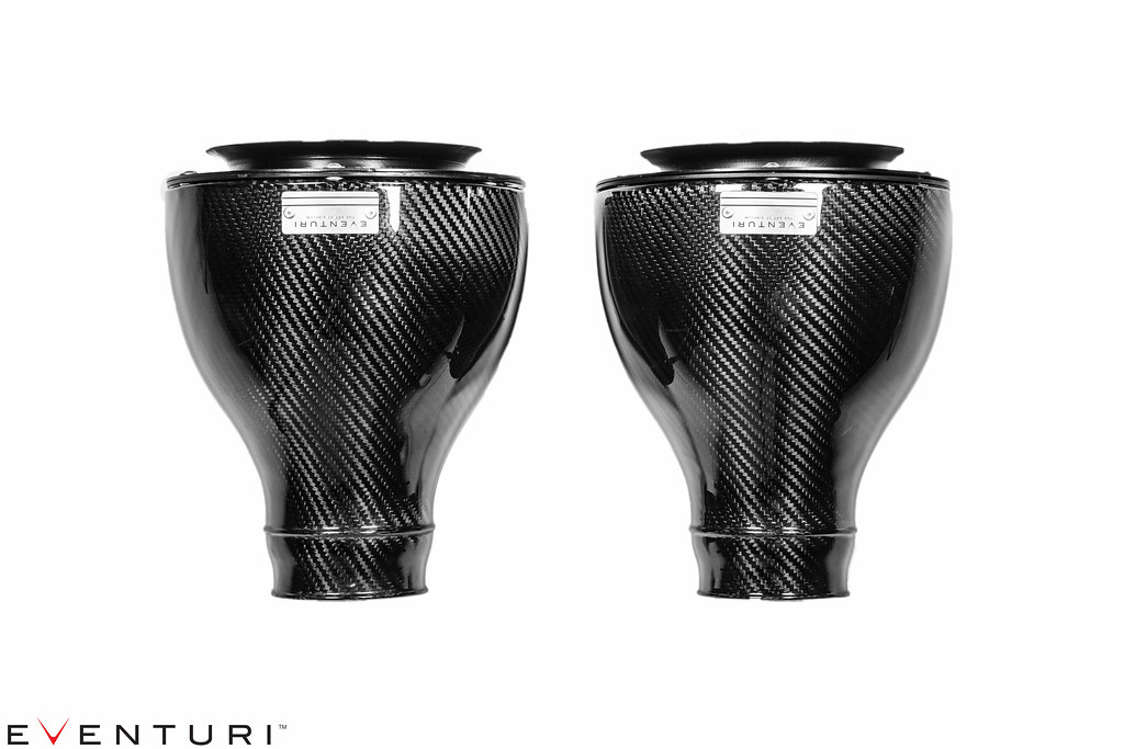
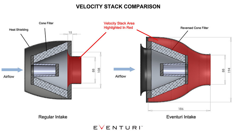
The filter housings comprise of the high flow filters, aluminium cowls and the carbon pods themselves. The carbon pods shroud the reverse mounted filter and smoothly shape the airflow down to the intake tubes. This smooth reduction in cross sectional area invokes the Venturi effect where the airflow accelerates whilst maintaining laminar conditions. It can be thought of as a large velocity stack – below is a diagram to show the comparison between our patent pending design and a regular intake system. Further details can be read in the Technology page.
Carbon Fibre Intake Tubes
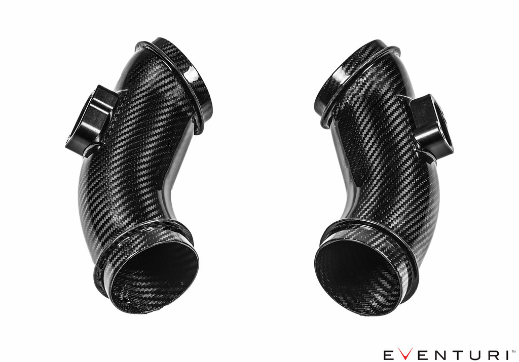
Our intake tubes are again crafted from 100% prepreg carbon fibre. Each tube has an integrated MAF sensor mount which is CNC machined from aluminium. The tubes smoothly connect the filter housings to the turbo inlets and eliminate the stock corrugated flexi-tubes which have a much more disruptive flow path. We ensured that the carbon tubes maintain a true circular cross section – even at the MAF boss for the best possible flow characteristics.
Carbon Fibre Air Scoops
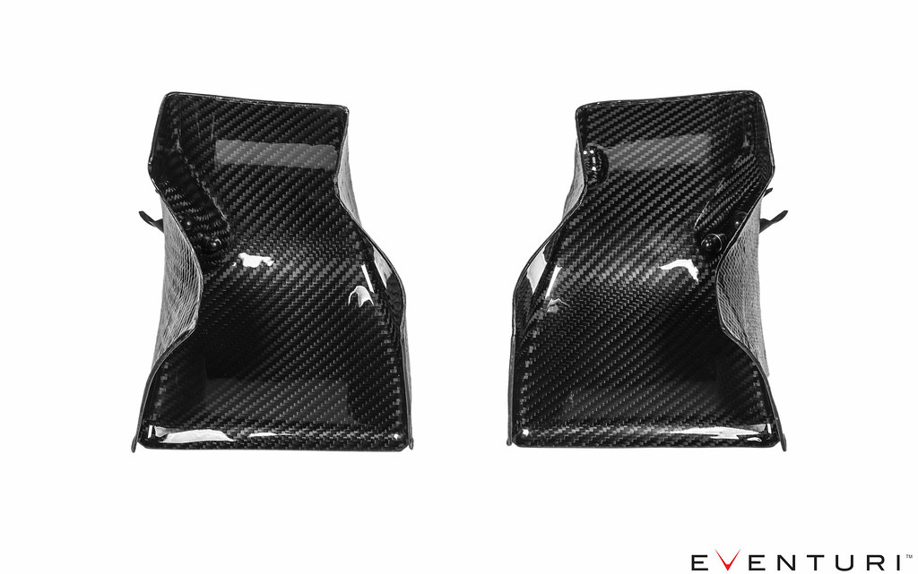
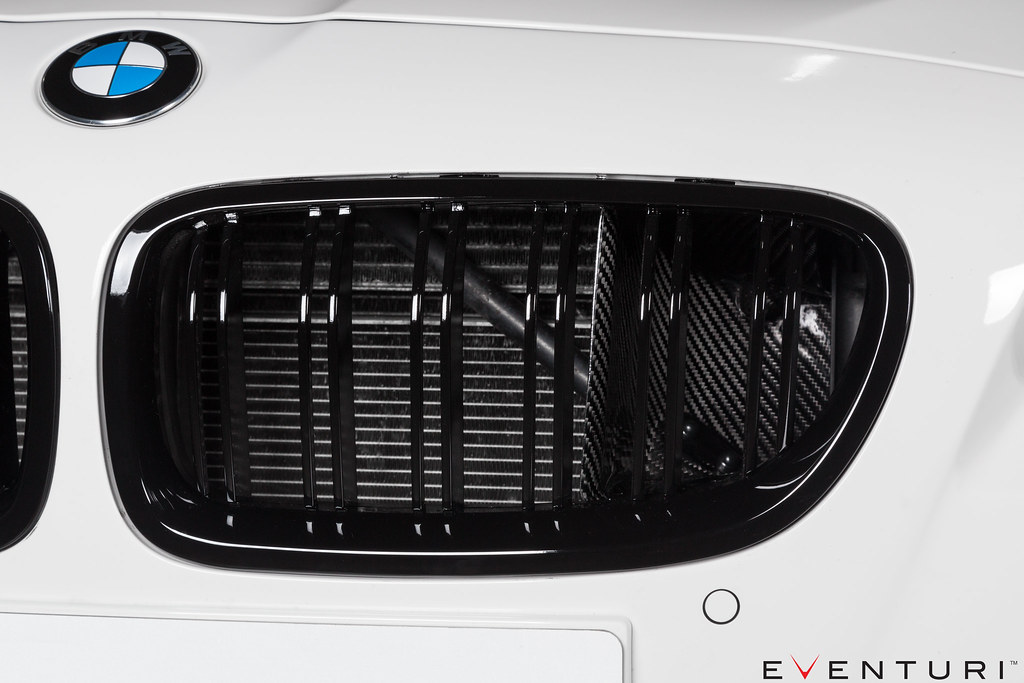
The final carbon components in this system are the front scoops – essential to direct ambient air to the filters.
The scoops were designed for maximum efficiency in directing the incoming air to the stock duct openings. Many aftermarket scoops have a large flat area almost perpendicular to the oncoming air – not great for channeling it into the ducts as the airflow just “hits” this flat portion and creates turbulence.
Unlike most aftermarket “scoops” the Eventuri Scoops have been designed extend from the stock duct openings all the way to the grills. In order to capture as much air as possible, the scoops are shaped to the same contours as the outsides of the grills and then smoothly channel ambient air through a continuous curve to the duct openings. CAD images to illustrate the shape:
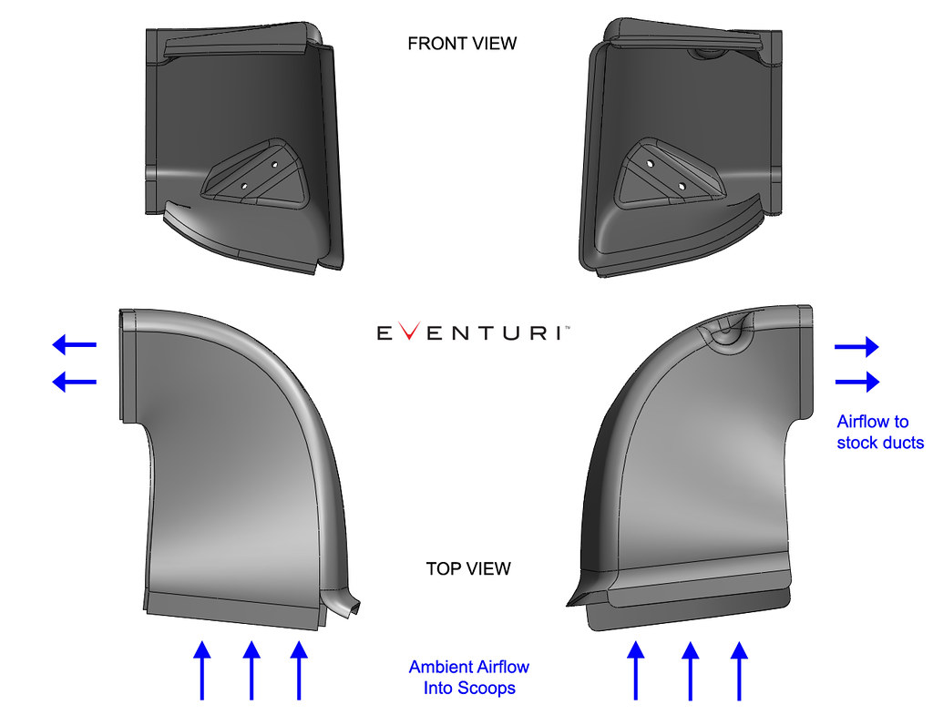
Having an effective cold air feed to the filters is an essential part of our design. Simply having some heat shields in place is not an effective means of avoiding heated air from entering the filters unless the shields create an air tight envelope around the filters. The scoops and shields in our system combine to provide the filter openings with ambient air and maintain low intake air temperature. To illustrate the effectiveness of this system, we put together this video showing our intake design on the F83 M4 which has the same scoop/duct design:
The scoops are simple to install – they snap onto the existing strut brace and are then held in position by the front grills.
Shields / Flow Deflectors
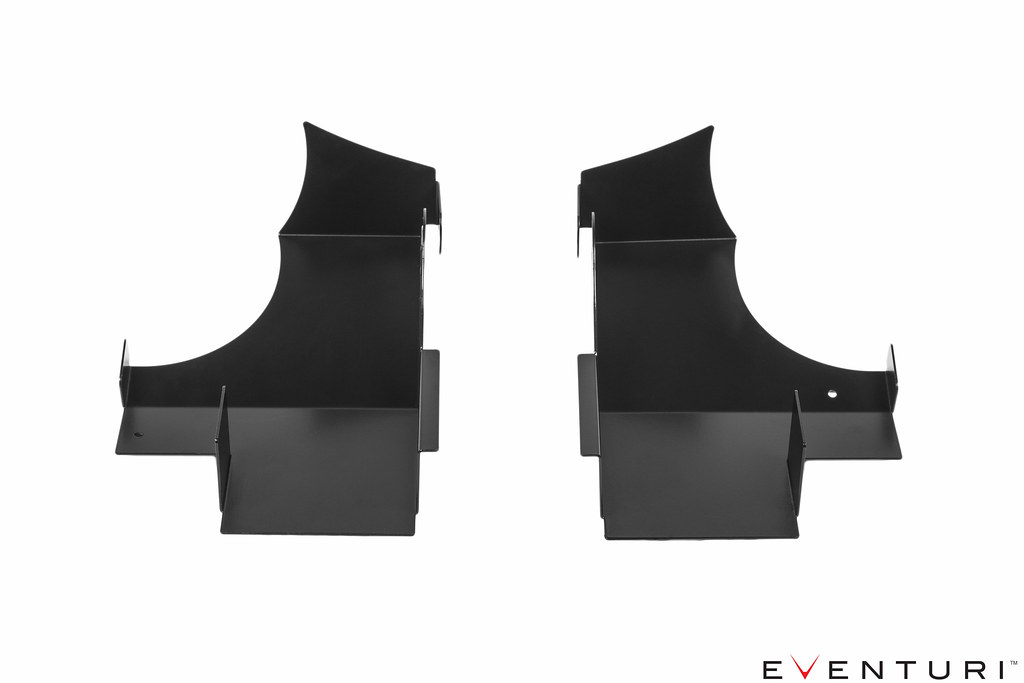
The filter housings are positioned with the openings nestled inside the flow deflectors. These deflectors capture the cold air coming in from the front scoops and help displace hot air from around the filter openings. Here is a CAD image to illustrate the configuration of the filter housings, deflectors and scoops. The gap between the scoops and deflectors is taken up by the stock ducts.
To illustrate – here are the left and right hand side intakes assembled as they would be in the engine bay with the tubes and ducts:
