Eventuri BMW M3/M4 (G8X) Carbon Fibre Air Intake – EVE-G8XM-CF-INT
Performance Gain: 13-18hp, 12-16ft-lb (Stock Tune)
Turbo Inlet Area Increased up to 160%
Filtration Area Increased up to 40%
Presenting an intake which truly sets a benchmark for the BMW G8X M3/M4 platform. We have carried out intensive R&D to develop an intake which not only improves on the stock M3/M4 but also is future proof in its capacity to cater for high powered builds well in excess of 1000hp. Our system is a complete redesign from the airboxes to the turbo inlets with the aim of reducing pressure loss while increasing the flow rate and keeping inlet temperatures low. We have maximised the usage of the available space to employ 2 custom made filters with a 40% larger filtration area than stock. These are used in our Patented Venturi housings to smoothly funnel the air to the turbo inlets. The inlets themselves are up to 160% larger in cross sectional area than stock and are designed with an advanced dimpled inner surface to reduce frictional losses between the flow and the wall boundary. By allowing a “cushion” of air at the wall surface, airflow is able to move through the inlets at higher flow rates with reduced pressure loss. This allows the turbos to draw air with less resistance and therefore reduce the wastegate duty cycle resulting in higher overall performance.
The Eventuri Difference
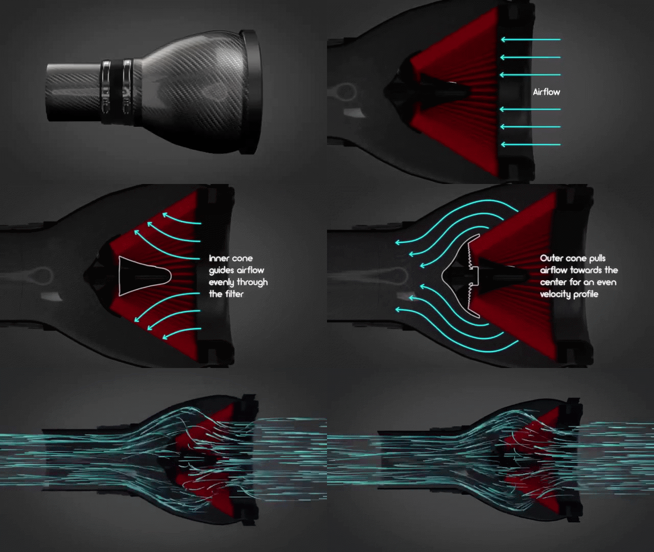
The G8X M3/M4 Eventuri system uses our Patented Carbon Fiber Housings with our Gen 2 bespoke filters, which provide an aerodynamically efficient airflow path from the filter to the turbos. Not just another cone filter with a heat shield but a unique design which invokes the Venturi effect and maintains laminar flow conditions to reduce the drag on the turbo. You can read more about the housing design and how it works
The Eventuri G8X M3/M4 intake system consists of a number of components engineered to perform a specific purpose and fabricated to the highest of standards. We use 100% pre-preg carbon fiber with no fibreglass which means we can achieve a smooth internal surface to maintain smoother airflow. Here are the details for each component and the design ethos behind them:
Each intake system consists of:
- 2 x Carbon Fiber Patented Venturi Filter Housings
- 2 x Bespoke High Flow Dry Cone Filters
- 2 x Carbon Fiber Inlet Ducts
- Carbon Fiber Intake Tube
- 2 Thermoplastic Turbo Inlets
- Laser Cut Stainless Steel Brackets
- Custom Flexible Hose
- CNC Machined Bracket Mounts and Reinforcement Rings
Dyno Testing
This intake has been independently dyno tested by BR Performance in Belgium. Tests were done back to back against the stock airbox and several runs were taken with each configuration. The car tested was without charcoal filters. We took the best results from the stock airbox and the best from the Eventuri system. The dyno results show a consistent gain throughout the RPM range which can be attributed to the turbos reaching peak boost earlier and with a lower wastegate duty cycle due to the higher efficiency of the intake system. This gain is despite the dyno cell temperatures rising from 11.8 deg C for the stock system tests to almost 16 deg C for the Eventuri tests. The performance gain translates on the road to increased part throttle and full throttle response with the car pulling much more eagerly to the redline.
IAT Testing
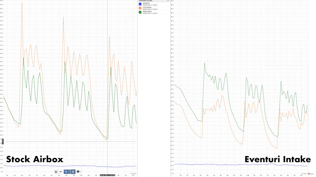
Turbo charged cars can build up a lot of engine bay heat which can be detrimental to performance if the intake system is not sealed against it. Even with intercoolers and charge coolers, it is important to minimise Inlet Air Temperatures (IATs) as these cooling devices work with an efficiency ratio so the output air temperature is affected by the input air temperature. Derestricting the intake by using open cones, even if heat shielded will inevitably pull in hot air from the engine bay. Our system being fully sealed solves this problem while still derestricting the flow path using bigger volumes. To demonstrate, we data logged air temperatures using thermocouples just before each turbo. Comparisons were taken between stock and Eventuri on the same day with the same ambient conditions. Our M3 was allowed to heat soak and then it was accelerated from 30mph to 90mph in 6th gear to measure the change in temperature across each run. At 90mph, throttle was released and brakes were applied to 30mph at which point the car accelerated again to 90mph. A total of 3 pulls were made with both intake configurations.
The first graph shows the temperatures on before both turbos with eth stock airbox on the left and the Eventuri intake on the right. Due to scaling, the axes are not perfectly matched between both graphs but the numbers can be clearly seen. As expected, the RHS of the intake showed similar data between stock and Eventuri since the flow path and materials are similar. However, the LHS intake shows a significant improvement in IAT for the Eventuri. This can be seen in the second graph where the 2 charts are overlaid. On each successive pull the Eventuri shows a lower IAT as compared to stock and also the spike in temperature as throttle is lifted is significantly lower with the Eventuri. This difference is down to the more direct flow path with the Eventuri and also the materials used in the turbo inlet.


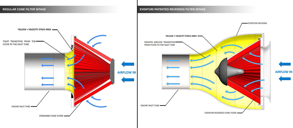
The filter housings comprise of our bespoke generation 2 filters, aluminium inlet cowls and stainless steel brackets. The carbon pod shrouds the reverse mounted filter and smoothly shapes the airflow down to the tube section which then connects to the turbo tubes. This changes the flow path from the OEM airbox where airflow enters the front of the airbox, changes direction by 90 degrees to travel through the panel filter and then changes direction again by 90 degrees to move through the tube section. Our system is a lot more direct with airflow entering the front of the filter housing and and moving into the tube section without any abrupt direction changes. The result is a smoother path from the filter to the turbo inlet tube and therefore the turbo is able to function with less drag.

BESPOKE CONE FILTER
In order to achieve the highest flow rate possible we designed a new filter element to make as much use of the space available in the engine bay as possible. This new filter has an outside diameter of 192mm or 7.6″ and when flow tested with a housing using a 4″ opening is able to flow up to 900 CFM at 28″ H2O. The filter medium is ISO tested to ensure that filtration is in line with OEM standards and is also dry. The filter is constructed with our signature flow cones to aid in the Venturi housing principle.
PATENTED TECHNOLOGY
Our patented filter housing has a smooth reduction in cross sectional area as it shrouds the filter and tapers down to the tubing. This geometry invokes the Venturi effect where the airflow accelerates whilst maintaining laminar conditions. It can be thought of as a large velocity stack – below is a diagram to show the comparison between our patented design and a regular intake system. Our bespoke filters aid the airflow moving through the housings and allow for an even velocity profile as the airflow exits the housings. Further details can be read in the Technology and Filters pages.

TURBO INLETS

The biggest restriction in the stock system are the turbo inlets. The G8X M3/M4 has an inlet for each turbo and we were able to significantly increase the sizes of both of them. By increasing their sizes, the turbos are able to pull in air with less restriction hence allowing for a quicker spool. In the following photos you can see the differences in the sizes. Although the benefit may be small for a stock car, we expect these larger inlets to be more beneficial for higher states of tune where the target boost pressures are increased.


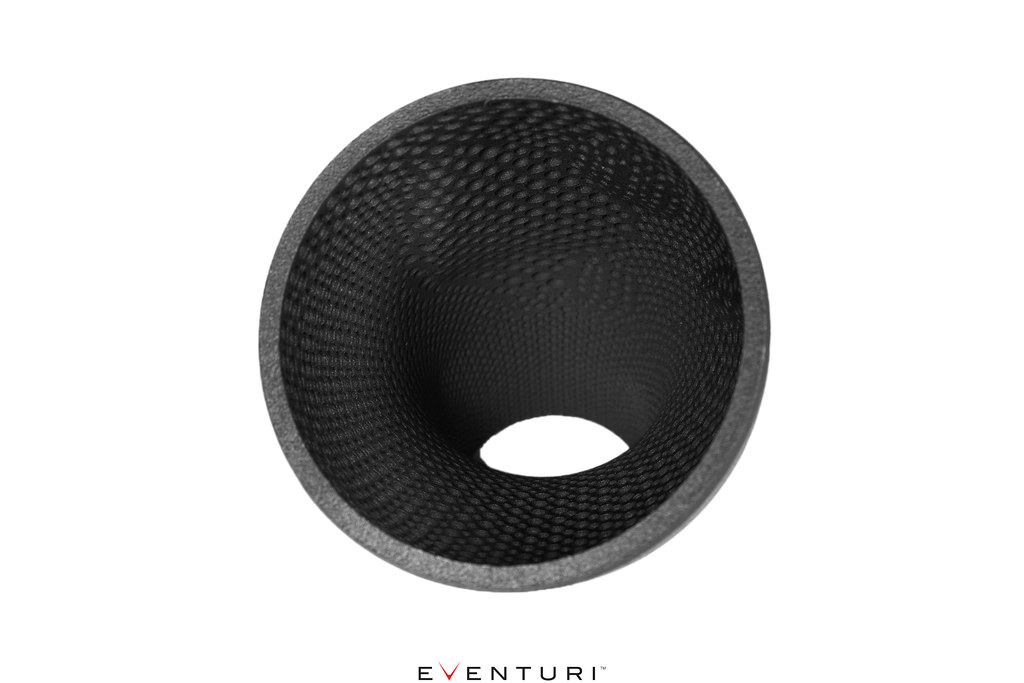
We could have finalised the designs here however, we wanted to push the boundaries further and introduce a novel dimpled pattern to the inside surfaces. In theory, small dimples can increase the flow rate by reducing the frictional pressure losses through a tube.

A lot of R&D went into simulating different sizes and shapes until we settled on an optimised version which demonstrated a higher flow rate through the inlets in comparison with a smooth surface. Applying such an intricate was only possible due to the advanced manufacturing technique we employed to make the inlets, where traditional methods would not have given the accuracy required. The dimples create an “air cushion” affect over the surface of the inlet which then allows the main body of air to “slip” with less friction through the body into the turbo. This results in a more even velocity profile in a dimpled tube with the net affect being a higher velocity for the same boundary conditions. Here are the CFD simulations showing the re-circulations in the dimples and the higher velocity in the dimpled tube. Further reading can be done from these scientific papers:


